Specifications
- 8 Digital output
- 8 Digital input
- 8 Analog output
- No external power required
- Simple ASCII command
- 3 command to communicate PC with PIC
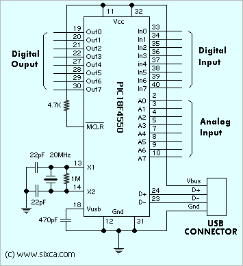
Figure Schematic
Project Hardware
The analog signal from the microphone was amplified using an op-amp and then digitized using the 16C745's analog-to-digital feature. If you are reproducing this project, I would recommend putting in a filter to remove the frequencies higher than the microprocessor's sampling rate. The digital data was buffered in the microprocessor and then set to the host computer over the USB connection. Since 'interrupt' method of transfer only allows 8 bytes of data transfered every 10ms, this limited the amount of data that could be transfered.
The following circuit connects the PIC to the usb cable. It is designed to be powered off the USB cable. The 6 MHz clock controls the internal oscillator.
The 'reset' switch, causes a reset condition which should cause most of the special registers to clear and the program to start again.
The value of R1 is not critical since it is only used as a pull-up for the MCLR (master clear) pin. The R2 resister is required by the USB specification and should be 1.5 kOhms. The capacitor C3, is not critical and simply stabilizes the Vusb pin voltage. The values of the capacitors, C1 and C2 can be in a range specified in the 16C745 specification (15pf - 69 pf) and may depend on the crystal that you use.
Check that USB power and ground connections are correct before connecting the chip. It is easy to get turn around between the cable pinout and the socket pin out.
The following circuit is used to power the electret microphone and then amplify the signal. The output signal is connected to one of the analog pins of the 16C745, we used pin 2, corresponding to AN0 (analog pin 0).

No comments:
Post a Comment