Monday, 26 March 2012

GREEN TECHNOLOGY PARKING SYSTEM

        As it week nine.I be asked to changed my fyp title to green technology and be do the project by group of two.My project basically about smart parking combine with green technology.For smart parking it makes easier for driver to find parking space.In the parking there will counting the parking space. When it show zero parking LCD will display 'FULL' so the driver will know that there is no parking in that place.We can survey the parking system by Visual Basic. This system will be placed at security place.
       This system will no use supply from MCB.This system will supply by the green technology.They are four types green technology that be used for supply to the system.We will be used Piezoelectric, kinetic, solar system and wind turbine.

Monday, 12 March 2012

HOW RFID WORKS


How does RFID work? A Radio-Frequency IDentification system has three parts:

A scanning antenna
A transceiver with a decoder to interpret the data
A transponder - the RFID tag - that has been programmed with information.
The scanning antenna puts out radio-frequency signals in a relatively short range. The RF radiation does two things:
It provides a means of communicating with the transponder (the RFID tag) AND
It provides the RFID tag with the energy to communicate (in the case of passive RFID tags).
This is an absolutely key part of the technology; RFID tags do not need to contain batteries, and can therefore remain usable for very long periods of time (maybe decades).
The scanning antennas can be permanently affixed to a surface; handheld antennas are also available. They can take whatever shape you need; for example, you could build them into a door frame to accept data from persons or objects passing through.

When an RFID tag passes through the field of the scanning antenna, it detects the activation signal from the antenna. That "wakes up" the RFID chip, and it transmits the information on its microchip to be picked up by the scanning antenna.

In addition, the RFID tag may be of one of two types. Active RFID tags have their own power source; the advantage of these tags is that the reader can be much farther away and still get the signal. Even though some of these devices are built to have up to a 10 year life span, they have limited life spans. Passive RFID tags, however, do not require batteries, and can be much smaller and have a virtually unlimited life span.

RFID tags can be read in a wide variety of circumstances, where barcodes or other optically read technologies are useless.

The tag need not be on the surface of the object (and is therefore not subject to wear)
The read time is typically less than 100 milliseconds
Large numbers of tags can be read at once rather than item by item.

Below is video tutorial, provided by Digi-Key and Texas Instruments, will answer the questions What is RFID and how does it work? and examine how the frequency of operation affects the characteristics of the system and in turn influences the choice of application.

                         RFID Technology and Applications


USB DATA ACQUISITION WITH PIC18

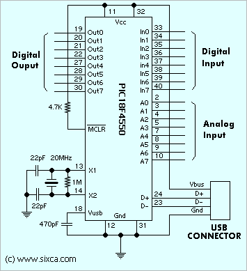
This project is simple and small component count USB data acquisition or USB DAQ. The main core of USB device is PIC18F4550 .The firmware for PIC modified from Microchip CDC library.

Specifications

- 8 Digital output
- 8 Digital input
- 8 Analog output
- No external power required
- Simple ASCII command 
- 3 command to communicate PC with PIC 


                                                                    Figure  Schematic


Project Hardware


The analog signal from the microphone was amplified using an op-amp and then digitized using the 16C745's analog-to-digital feature.  If you are reproducing this project, I would recommend putting in a filter to remove the frequencies higher than the microprocessor's sampling rate.  The digital data was buffered in the microprocessor and then set to the host computer over the USB connection.  Since 'interrupt' method of transfer only allows 8 bytes of data transfered every 10ms, this limited the amount of data that could be transfered.
The following circuit connects the PIC to the usb cable. It is designed to be powered off the USB cable. The 6 MHz clock controls the internal oscillator.

The 'reset' switch, causes a reset condition which should cause most of the special registers to clear and the program to start again.

The value of R1 is not critical since it is only used as a pull-up for the MCLR (master clear) pin. The R2 resister is required by the USB specification and should be 1.5 kOhms. The capacitor C3, is not critical and simply stabilizes the Vusb pin voltage. The values of the capacitors, C1 and C2 can be in a range specified in the 16C745 specification (15pf - 69 pf) and may depend on the crystal that you use.

Check that USB power and ground connections are correct before connecting the chip. It is easy to get turn around between the cable pinout and the socket pin out.


Circuit Diagram showing USB connections
The following circuit is used to power the electret microphone and then amplify the signal. The output signal is connected to one of the analog pins of the 16C745, we used pin 2, corresponding to AN0 (analog pin 0).


Microphone Powering Circuit


SD MEMORY CARD INTERFACE


SD memory cards, especially the ones under 1GB are cheap, relatively easy to interface and provide vast amounts of memory for imbedded control.

This device lets reading to sd cards through your serial port. Communication is in ASCII so you just need a terminal program to access it. 

                                          The Hardware

SD sockets are available from SparkFun Electronics. The socket needs to be surface mounted so it was placed on the foil side of the single sided board. The connections are close to 0.1 inch centers, so the layout was not difficult.

The PIC16F819 was chosen for its hardware support for SPI. (SD cards will usually work through an SPI interface) Running at 20Mhz, the SPI port clocks data at 5Mhz, and the serial communication is able to run at 115200 baud in software.
A quick look at the schematic shows one way to interface the 5 volt PIC to the 3.3 volt SD card. A red LED drops the 5 volt supply by about 1.8 volts to feed about 3.2 volts into the card. This is within the operating range.

Signals from the PIC go through a 1k/2k voltage divider to feed signals to the card. Signals back from the card feeding SDI input are a problem because the PIC uses schmit-trigger inputs in SPI mode requiring 3.5 volts for the high level. The circuit provides a 0.6 volt shift so the output of the card back to the PIC ranges from 0.6 to 3.8 volts. Cheesy, but it works.

The Software

The main issue with the software is configuring the SPI port. After a lot of diddling around, the proper setup seems to be: SMP=1, CLE=1, and CKP=1. See the software listing for the complete setups of SSPSTAT and SSPCON registers in sspinit. The routine that writes to the card also reads it, since, in SPI, read and write are simultaneous operations.

Once connected to a terminal program (115200 baud, 1 stop bit, no parity, no handshaking), the following commands are available:
CommandFunction
S
Select Card
D
Deselect Card
Zddd
Send ddd bytes of clocks
W xx xx xx xx xx ...
Send series of (hex) bytes
Cdd ddddd
Send command dd containing
address 512*ddddd
Xddd xx
Send ddd bytes of (hex) value xx
Rddddd
Read ddddd bytes from card
Ctrl-CResend last command
ddd = decimal value, xx = hex value
Commands can be combined on a single line, for example...
C17 2 R520
Command 17 (read sector) at address 1024 (start of sector 2) followed by read back 520 bytes.
C0 0 R2 C1 0 R2 C1 0 R2
Setup board for SPI, read status, init board, check status, check init, read status.
Note that the C command generates an effective 'sector address' by multiplying by 512. It also generates the mandatory 95 (hex) CRC that is only required for Command 0 to put it in SPI mode. After that, the CRC is not required for any other commend.
If you want to issue a command the needs specific parameters other than a sector address, you need to use the W command with everything in hexadecimal.
Eventually, this device is to be made into an SD card programmer/reader. For now, its a way to probe the operation of various manufacturers cards.